Product Summary Multi-FPGA Partitioning
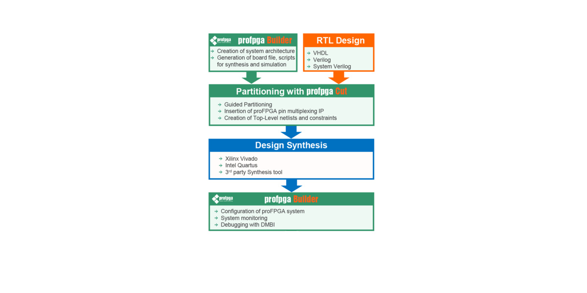
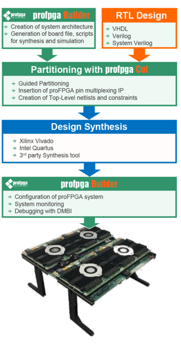 The new proFPGA Cut is a perfect extension to the proFPGA Product Portfolio. The Software includes a guided partitioning tool that handels all required tasks from importing RTL files till exporting it for synthesis and place & route. In Addition its is designed to reduce the design implementation time to a minimum. The proFPGA Cut software is optimized for proFPGA hardware and takes full advantage of the system’s modular and flexible interconnection architecture. Besides the GUI mode, the tool also offers a command line mode which allows the user to script all processes and to fully integrate it into its automated design flow.
The proFPGA systems handle complex ASIC and SoC Designs up to 2 Billion ASIC gates and give design and verification engineers unprecedented speed for high-speed verification and bug hunting to shorten the time to market by eliminating costly re-spins and by providing early prototypes for software development and/or to end customers.
Because of the fast-growing design sizes and the increasing number of required FPGAs, design bring-up and design partitioning are very challenging and time consuming tasks.
Due to the fact that the performance is the most important and critical factor, PRO DESIGN pursues with its new proFPGA Cut tool a different approach. Instead of offering a completely automated “push button” flow with limited control, proFPGA Cut guides the user through the multi-fpga partitioning process step by step from importing RTL to the export to the synthesis tool. Consequently, the user has still full control over the design and the tool supports him to shorten this usually time consuming and complex process. proFPGA Cut offers the insertion of pin multiplexing IPs, logic optimization, constraints setting, conversion of multi-point interconnections into point-to-point interconnections, semi-automated movement of instances/ nets, the possibility of scripting etc.
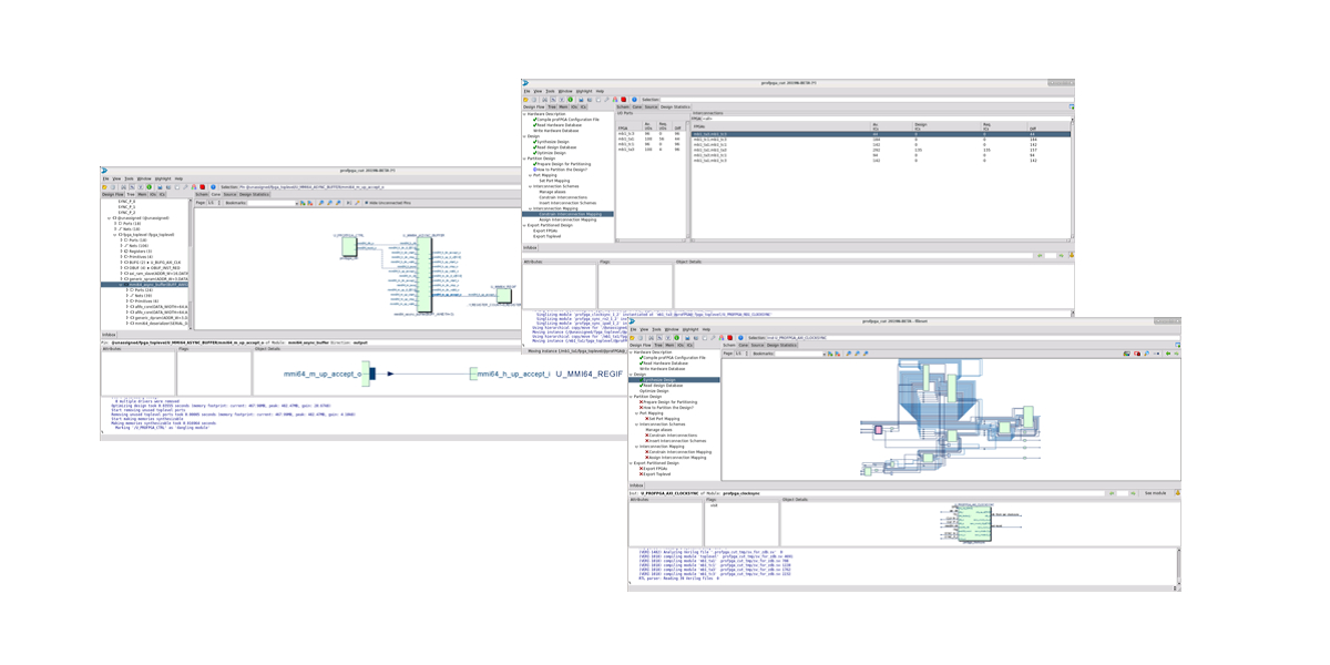
proFPGA CUT - Visualizer
The easy-to-use software guides the user step-by-step through the design implementation flow, which gives him a structured overview. A tree structure is used to display the design hierarchy. All external access ports (IOs) are shown and can be mapped to physical pins. Furthermore the visualizer displays all design interconnections between FPGAs and how they are physically mapped. In addition, proFPGA CUT can handle different FPGA technologies and a combination of these.
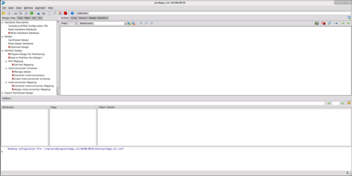 |
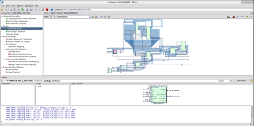
proFPGA CUT - Main Window With the design flow view on the left, schematic view on the right and terminal outputs at the bottom, proFPGA CUT is clearly structured. |
|
|
proFPGA CUT - Schematic View The Schematic Window displays a complete module
|
 |
|
 |
proFPGA CUT - Ressources Window The design statistics window provides feedback about the required resources of the design and the available resources of the hardware. If no hardware database is loaded only the design resources will be displayed. |
|
|
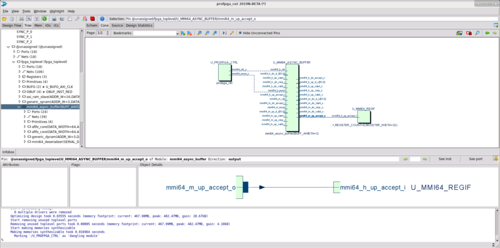
proFPGA CUT - Cone View The Cone Window displays schematic excerpts (paths, cones, etc.) and is used for Incremental Schematic Navigation. It allows interactive incremental is closure of the schematic, even across hierarchy borders (giving a kind of “flat-view” on the database).
|
 |
|
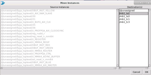 |
proFPGA CUT - Move Instances Window to define destination FPGAs for selected design parts, which should be moved. |
|
|
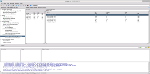
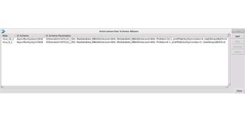
proFPGA CUT - Pin multiplexing Schemes IC (interconnection) schemes are especially used to implement multiplexing. Thus, it is necessary to perform this step when the design uses more interconnections between two FPGAs than the hardware provides. Different interconnection schemes can be created for one design, including pin multiplexing factor, data rate, IOSTANDARD and different
|
 |
|
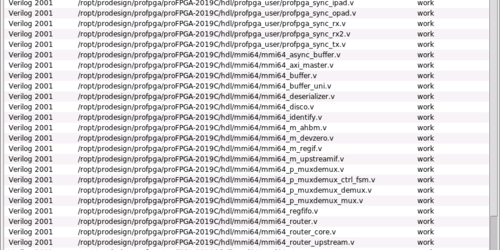 |
proFPGA CUT - Synthesize Design Files At first the user needs to define all input files for the design and the design toplevel. Those can bei either in Verilog, System Verilog or VHDL. |
|
| 產品文件:proFPGA 產品總覽 (EN) |