產品特色
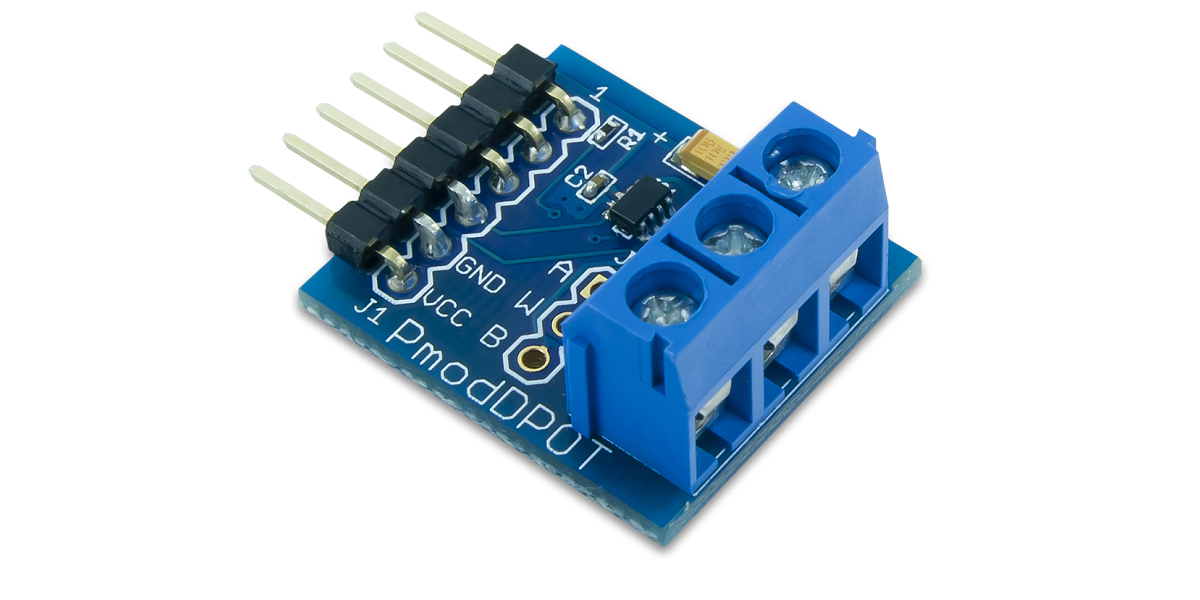
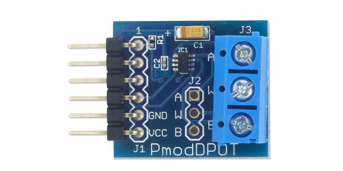
DIGILENT Pmod DPOT 是由 Analog Devices AD5160 驅動的數位電位計,透過 SPI 介面對晶片進行編程,在 60Ω 和 10,000Ω 範圍內設置想要的電阻。
- 使用 Analog Devices AD5160
- 8 位元解析度的數位電位器
- 可設置電阻範圍:≈60Ω至10,000Ω
- 適用於各種設計的小型 PCB 尺寸 (2.3公分×2.0公分)
- SPI 介面的 6 pin Pmod連接器
Pinout Description Table
| Pin | Signal | Description |
|---|---|---|
| 1 | ~CS | Chip Select |
| 2 | MOSI | Master-Out-Slave-In |
| 3 | (NC) | Not Connected |
| 4 | SCLK | Serial Clock |
| 5 | GND | Power Supply Ground |
| 6 | VCC | Power Supply (3.3V/5V) |
Any external power applied to the Pmod DPOT must be within 2.7V and 5.5V; however, it is recommended that Pmod is operated at 3.3V. Users must also ensure that any voltage applied to the outside terminals is between GND and VCC.
Interfacing with the PmodThe Pmod DPOT communicates with the host board via the SPI protocol. By bringing the Chip Select (CS) line low, users may then provide 8-bits of data on the falling Serial Clock (SCLK) edge in SPI Mode 0. Once the 8 bits of data have been transferred, the rising edge of the CS line loads the data into the internal register DAC, whereupon the resistance between terminals is set. The Pmod DPOT can be utilized in two different styles: a rheostat where users set a desired resistance between one outside terminal and the wiper terminal or in a voltage divider mode where the two outside terminals are powered at set voltages and a ratio of resistance is specified. Equations for the programmable resistance values and output voltages are provided from the AD5160 datasheet below: Equation for the resistance between the wiper terminal (W) and the B terminal, where D represents the sent 8-bit value in decimalHere, RAB represents the nominal resistance of 10 kΩ and RW is the wiper terminal resistance of 60 Ω. Equation for the resistance between the wiper terminal (W) and the A terminal, where D represents the sent 8-bit value in decimalHere, RAB represents the nominal resistance of 10 kΩ and RW is the wiper terminal resistance of 60 Ω. Equation for the output voltage of the wiper terminal (W) in the voltage divider setup, where D represents the sent 8-bit value in decimalHere, RWA and RWB are the resistances calculated in the two above equations and VA and VB are the voltages applied at terminals A and B, respectively. Care must be taken to ensure that current flow between the wiper terminal and either terminal A or B must be limited to a pulsed ±20mA or a continuous 4.7mA so that the power dissipation capabilities of the on-board chip is not exceeded.
| 通訊協議/介面:SPI | |
| DIGILENT Pmod Interface Specification類型/版本:TYPE 2 / 1.2.0 |
|
| 產品文件:產品規格│原理圖 │ 資源中心 | |
| 產品編號:410-239 |
|
| 線上商店:商品連結可線上刷卡/享運費補助! |


